The Getting started tutorial helps you to become familiar with the Instant Terra interface and to create your first terrain.
- The Interface at startup
- Moving in the 3D space
- Setting your preferences
- Working with nodes
- Opening the parameters
- Creating your first terrain
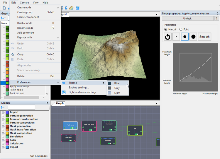
The Interface at startup
This is the Instant Terra interface at startup. It consists of a visual representation of a terrain in the Viewport and the default nodes composing the terrain in the Graph, including:
- Graph explorer: The Graph explorer is where you manage all the nodes and resources used in a project. It lists the various types of nodes as displayed in the Graph editor and updates in real time when you move a node.
- Models: The Models window displays a list of all the nodes that you can use in a project. You can sort the nodes by category or alphabetically, search them, and drag and drop them into the Graph editor.
- Viewport: The Viewport is where you see the real-time updates of the changes you make to your terrain. When you move the camera, link a node, or change a node parameter, the results are seen immediately in the Viewport.
- Graph: The Graph editor is where you do most of your work. Here, you build your terrain by linking Instant Terra's nodes via their connectors. You add, organize, and link nodes together to create your terrains./li>
- Main menu: The main menu gives access to Instant Terra's features.
- Toolbar: The toolbar gives quick access to some of Instant Terra's features.
Navigating in the 3D space
First, let's see how to move the camera in the Viewport's 3D space.
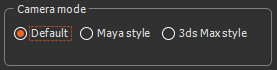
The default camera is the Instant Terra camera, but you can select one of the three different key and mouse combinations - Default, Maya-style, and 3ds Max-style cameras - to pan in the Viewport (see the Camera menu) for more details on how to toggle between the different cameras).
- To pan the terrain in space, left-click, hold the mouse button, and drag the mouse.
- To rotate the camera around the area of the terrain under the mouse cursor, right-click on an area, hold the right mouse button, and drag the mouse.
- Scrolling the mouse wheel allows you to zoom in and out in successive stages.
- When you click the mouse wheel, you zoom in or out of the terrain with the focus on the cursor position.
Setting your preferences
Before you get started creating your project, you may want to set up some parameters, depending on your preferences.
- Camera type: You can choose from either the default camera, the Maya style camera, or the 3dx Max-style camera, depending on which type of camera you usually use. Select Camera > Camera settings... to open the camera settings dialog.
- Light: Toggle between the light presets and adjust the sun's light and the ambient light to achieve an effect on a terrain under different lighting conditions. Select Edit > Preferences > Light settings... to open the parameters.
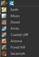
- Terrain colors: Choose a default terrain color from the eight default color ramps in the drop-down menu in the toolbar.
- Theme: The default theme is blue, but you can change it to gray, or light, depending on your preference. Select Edit > Preferences > Theme and choose a color to set the theme of the application.
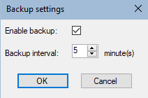
- Automatic backup: Instant Terra automatically backs up the current project in the same directory, once the project has been saved. You can change the backup interval and enable/disable the backup. Select Edit > Preferences > Backup settings... to open the automatic backup settings dialog and change the default values.
Working with nodes
Let's see now the possible interactions in the Graph.
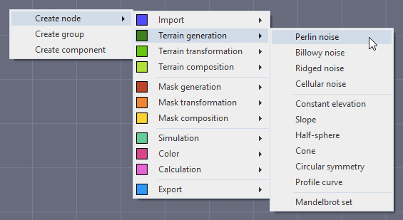
When you right-click in the Graph, you access the Create node menu, which contains all the nodes that can be added to compose the terrain. Each node is a mathematical operation that combines with others to create an increasingly rich graph.
See the Node reference guide for details on all the nodes.
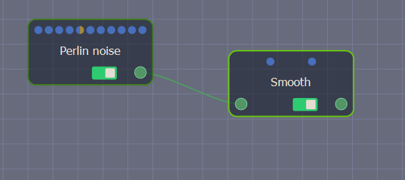
By left-clicking on the node's output connector and dragging the mouse to an input connector, you create a link that lets you connect it to another node. Once this new node is linked, its results are added to the previous nodes that make up the terrain.
You can also add and link nodes using the Fast-creation menu. Click the left mouse button on a connector or optional connector and drag the mouse. Release the mouse in an empty area to display the Fast-creation menu, which lists the compatible nodes.
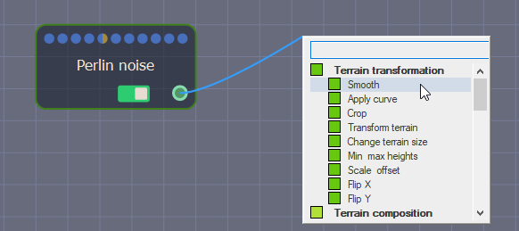
Select a node or search for a node and select it. The new node appears in the Graph editor linked to the previous node's output connector.
To select a node or several nodes:
- To select a node, simply click on it in the Graph.
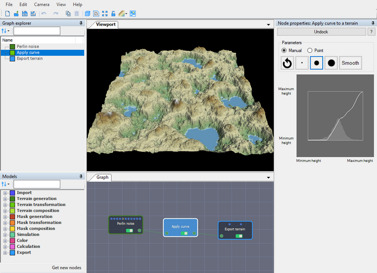
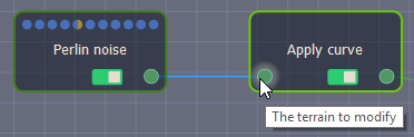
When a node is selected, if its computation is associated with a terrain or a mask, the terrain or mask is displayed in the Viewport. In the example below, clicking on the Apply curve shows the computation of this node with the Perlin noise terrain generator.
- To select several nodes one after another, press left-click+Ctrl.
- To select multiple nodes, press Shift and drag the mouse over the nodes to select.
- To move a node in the Graph, left-click, hold the mouse button, and drag the mouse.
- To delete a selected node (s) or link (s), select Edit > Delete or press the Del key.
Opening the parameters
When you double-click on a node, a new window opens with its parameters. You can modify the parameters and see the result directly in real time in the Viewport.
Some nodes have no parameters.
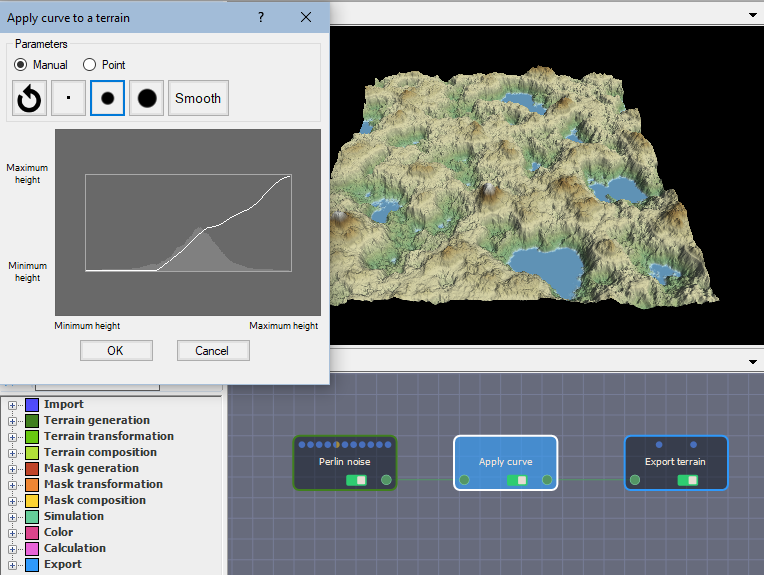
For more details on a node, simply click on the question mark in the parameters window title bar to access the relevant page in the documentation. We have also posted short video tutorials on YouTube on some specific nodes.
Creating your first terrain
In this section, you will create a terrain by composing two terrain generators and a mask, and adding erosion simulation.
- Clear the Graph by pressing Shift+left-click to select the default nodes and pressing the Del key to delete them.
- Right-click and select Create node > Terrain generation > Perlin noise and Slope to add these two generator nodes to the Graph. The Perlin noise node is one of the generators most frequently used to create a terrain. The Slope node creates a terrain plane with an editable inclination and orientation.
- Double-click on the Slope node to open its parameters and change the height in Set inclination angle to create a constant height of 400 meters.
- Select Create node > Terrain composition > Add to add the Add node, which allows you to combine the parameters of the two input generators, and link the nodes.
The new terrain has both the 400 m height of the Slope node and all the parameters inherited from the Perlin noise node.
- Now, drive this composition using a mask. Right-click on the Add node, select Replace with any node, and select the Sum using mask node.
- This composition node now requires a mask to work. Right-click and select Create node > Mask generation > Painted mask and link the nodes.
- For now, there is no difference between the Sum using mask node and the Perlin noise node. This is simply due to the fact that the Painted mask is black, so the Slope node parameters are not taken into account. You need to edit the mask and add white areas to the terrain.
Double-click the Painted mask node to open its parameters and check the Edit mask box.
Paint the mask directly in the Viewport.
In the place where you painted, the Painted mask is white, the Perlin noise mask retrieves the Slope node properties, and the terrain is elevated to 400 m.
- If you are not satisfied with the results, switch to the Darker brush to delete the mask.
- Reset the mask by clicking on Change mask and then Clear mask.
What is interesting now, rather than painting with pure white, is to set the brush intensity to 0.15 and the fall-off to 0.5 to get a much more nuanced composition on the terrain.
- Draw the mask.
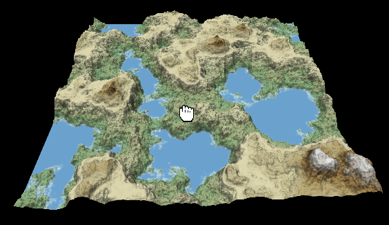
Here is the result.
- Right-click in the Graph and select Create node > Simulation > Hydraulic erosion to add a node that will create more realism on the terrain. This node creates realistic erosion and deposition effects caused rainfall and river flows.
Here is the result.
At this point, if you are not satisfied with
the result, click on the Lock icon in the Toolbar
 or press the space
bar on the keyboard to lock the Viewport on the selected node. This
allows you to go back to any previous node in the graph and modify
the parameters while keeping the current view in the
Viewport.
or press the space
bar on the keyboard to lock the Viewport on the selected node. This
allows you to go back to any previous node in the graph and modify
the parameters while keeping the current view in the
Viewport.
- Once you are satisfied with your terrain, export it to a 3D software package. To do this, either select Create node > Export > Export mesh to export the terrain as an .fbx file...
or select Create node > Export >
Export terrain to export the terrain as a heightmap. In
this node, you can preview the result in the Viewport using the
icon in the
toolbar or the M keyboard shortcut. All you need to do now
is choose the appropriate export format.
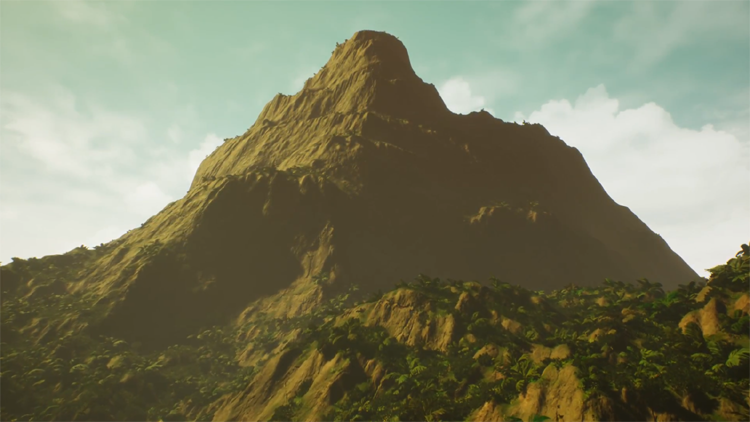
Here is the result once you have imported your terrain into a game engine, such as Unreal Engine.