About connectors
Each node has one or more connectors, represented by circles. There are three types of connectors:
- Required input connectors: These connectors receive data, such as a terrain or a mask, from another node. All input connectors must be connected so that the operation associated with the node can be executed.
- Optional input connectors: Optional connectors
link to a Calculation node or a mask node and replace the input
value in the linked node's parameter.
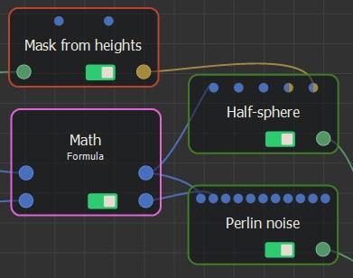
- Blue connectors link to Calculation nodes (Formula, Constant, etc.).
- Bi-color connectors link to either a Calculation node or a mask.
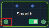
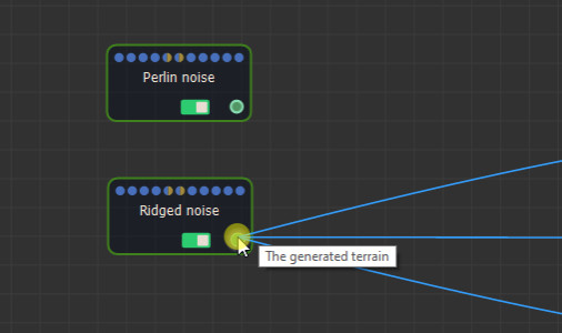
When you click on a connector, the Viewport displays the data associated with this connector, whether it is a terrain, a mask, a color map, or a color map. For example, when you click on the Rock erosion node optional connector linked to the painted mask, the painted mask appears in the Viewport.
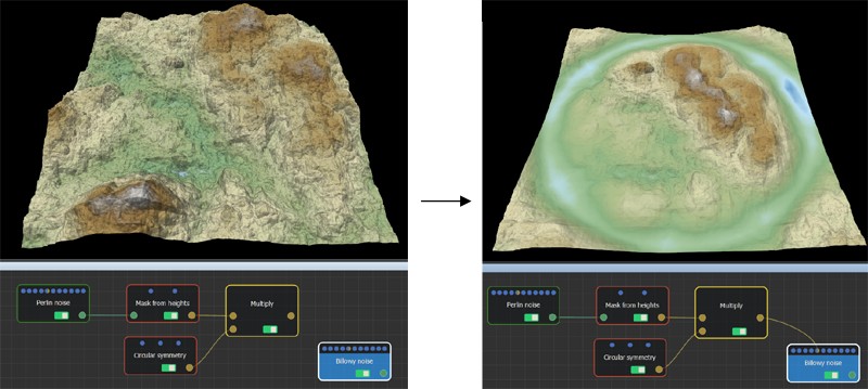
When using masks, you can drive one parameter of the output terrain to give a variable result over the terrain.
- Output connectors: These connectors correspond to new data, such as a terrain or a mask, calculated by the node.
About links
Links connect node connectors. An input connector must link to an output connector and the connectors must be of the same type, for example terrain connectors; it is not possible to connect a terrain connector to a mask connector.
Connecting nodes with a link
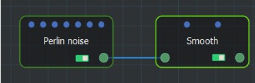
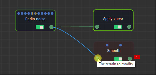
To connect nodes with a link, click on a connector on the first terrain and drag the mouse cursor to the connector on the second terrain, and release the mouse button.
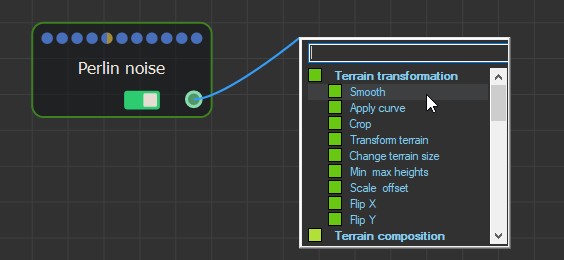
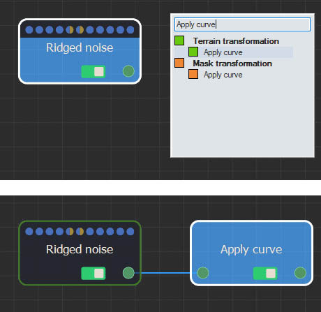
You can also click the left mouse button on a connector or optional connector, drag the mouse, and release it in an empty area to display the Fast-creation menu, which lists the compatible nodes. Select a node from the list to link it automatically from the output connector.
See Creating a node for more information on the different ways to add nodes.
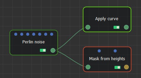
You can create several links from one output connector.
When creating a new node while an existing node is selected, Instant Terra will automatically connect the new node to the existing node, when possible, so you can create several nodes in a row, which are linked automatically.
For example, when you type TAB Ridged ENTER TAB Apply ENTER TAB Smooth ENTER, you achieve:
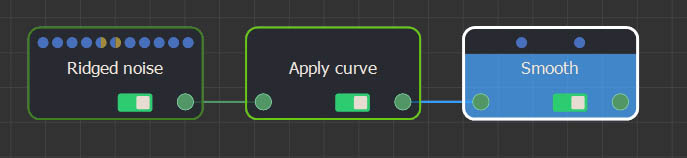
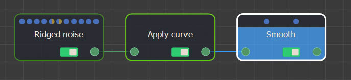
You can also use the keyboard shortcuts to create the nodes. For example, when you type NNR NTAC NTSM, you achieve:
Forbidden links
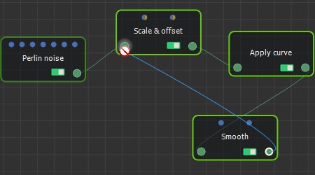
If the mouse cursor changes into a "no-entry" sign, it means that the two connectors cannot be connected together.
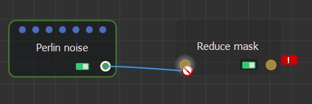
This is the case if the two connectors are two input connectors or two output connectors, or if they do not have the same type (e.g. terrain and mask). For example, the Perlin noise node generates an output terrain, but the Reduce mask node expects an input mask, so they cannot be connected.
It is also forbidden to create a new link that would create a cycle inside the graph.
Changing a link
To change a link, i.e. point it to another connector, click and hold the mouse button the connector to detach it, drag the mouse cursor to another new connector, and then release the mouse button.
Duplicating a link
Click on the input connector while holding down the Ctrl key to duplicate a link.
For example:
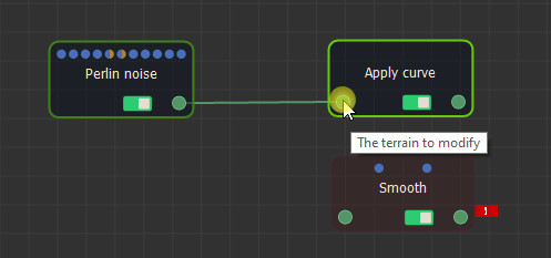
Click on the input connector while holding down the Ctrl key to duplicate a link.
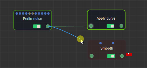
The link is duplicated.
You can connect it to a new node.
This feature is particularly useful when the two connected nodes are very far apart.
You can duplicate a link even if the starting node is not visible.
Moving several links simultaneously
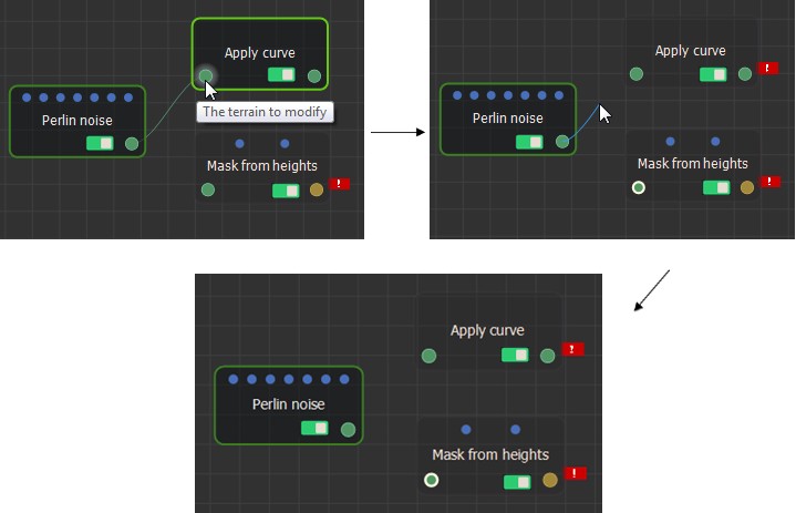
Move several links simultaneously by clicking on the start connector while holding down the Shift key.
For example:
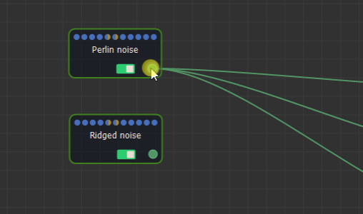
Click on the start connector while holding down the Shift key.
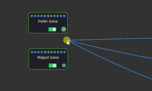
You can then move all the links at once and plug them into another node.
Swapping links
Swap two links using the contextual menu or the X key.
For example:
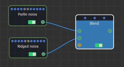
Starting position
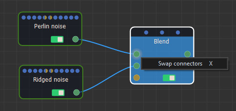
Opening of the contextual menu on one of the two connectors to swap.
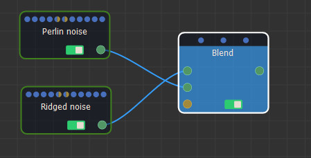
End position
You can use the X keyboard shortcut when a connector is selected, or when the mouse cursor is positioned over a connector.
Deleting a link
To delete a link, either:
- Click on one of the two connectors connected by the link, keep the mouse button pressed, move the mouse cursor to a place where there is no node, and then release the mouse button.
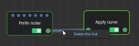
- Right-click on a link and select Delete this link.
- Select a link, press the Delete key.
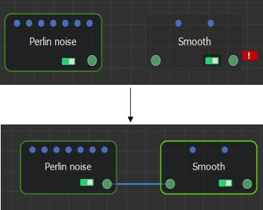
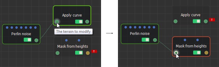
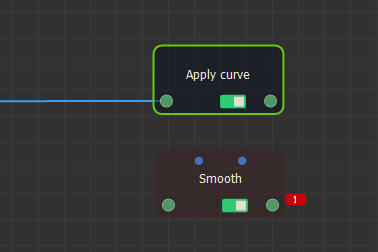
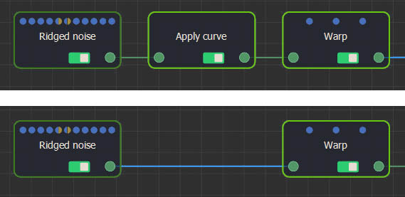
When removing a node and that node is linked on the left and the right, Instant Terra keeps the link when possible. For example, when deleting the Apply Curve node:
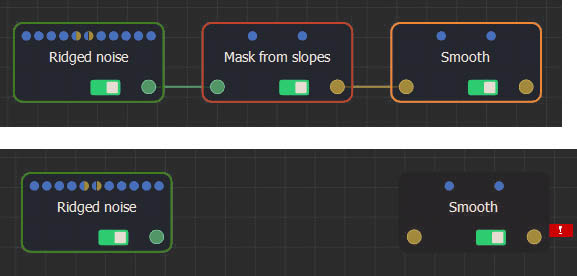
When the links are of different types, they cannot be kept, for example:
Adding and moving control points
To add control points to a link to control its shape, right-click and select Add control point in the contextual menu.
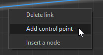
A control points is then created on the link.
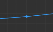
Move the control point by clicking on it with the left button and then moving the mouse while keeping the button pressed.
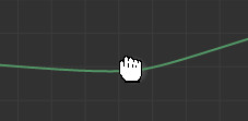
Create as many control points as you want on a link.
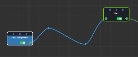
When you move one of the two nodes connected by a
link, the control points on this link do not move. However, if you
move the two nodes at the same time, the control points also
move.
When copying nodes, the control points are not copied: this
behavior is "by design".
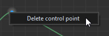
Deleting a control point
To delete a control point, click with the right mouse button on the control point and in the contextual menu, select Delete control point.